Magnetic Resonance - Technology Information Portal Welcome to MRI Technology
Info
  Sheets

Out-
      side


 'Inversion Recovery Spin Echo' 
SEARCH FOR    
 
  2 3 5 A B C D E F G H I J K L M N O P Q R S T U V W X Y Z
Result : Searchterm 'Inversion Recovery Spin Echo' found in 1 term [] and 0 definition [], (+ 18 Boolean[] results
previous     6 - 10 (of 19)     next
Result Pages : [1]  [2 3 4]
MRI Resources 
Mobile MRI - MRI Technician and Technologist Jobs - Absorption and Emission - Liver Imaging - Patient Information - Pregnancy
 
CHORUS 1.5Tâ„¢InfoSheet: - Devices -
Intro, 
Types of Magnets, 
Overview, 
etc.MRI Resource Directory:
 - Devices -
 
www.isoltech.co.kr/english/product/default.htm 
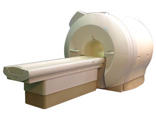
'Next generation MRI system 1.5T CHORUS developed by ISOL Technology is optimized for both clinical diagnostic imaging and for research development.
CHORUS offers the complete range of feature oriented advanced imaging techniques- for both clinical routine and research. The compact short bore magnet, the patient friendly design and the gradient technology make the innovation to new degree of perfection in magnetic resonance.'
Device Information and Specification
CLINICAL APPLICATION
Whole body
CONFIGURATION
Short bore
Head, C-spine, L-spine, TMJ, Knee, Shoulder, General purpose, Phased Array System: 4 digital receiver channels (Up to 12 channels)
Optional
SYNCHRONIZATION
ECG/peripheral: Optional/yes, respiratory gating
PULSE SEQUENCES
Spin Echo, Gradient Echo, Fast Spin Echo, Inversion Recovery (STIR, Fluid Attenuated Inversion Recovery), FLASH, FISP, PSIF, Turbo Flash ( MPRAGE ),TOF MR Angiography, Standard echo planar imaging package (SE-EPI, GE-EPI), Optional: Advanced P.A. Imaging Package (up to 4 ch.), Advanced echo planar imaging package, Single Shot and Diffusion Weighted EPI, IR/FLAIR EPI
IMAGING MODES
2D/3D, Travelling Sat, Multi-Slab 3D, MTC and TONE Pulse Sequence, Fat/Water Suppression, Presaturation (up to 6 bands), Flow Compensation using GMR pulse, Multi-Slice, Multi-Group Imaging
SINGLE/MULTI SLICE
Image reconstruction time (2562 ) : 0.02 s
FOV
40 cm
BORE DIAMETER
or W x H
58 cm diameter (patient)
MAGNET WEIGHT
4050 kg
H*W*D
233 x 206 x 160 cm
COOLING SYSTEM TYPE
Water-cooled coil and air-cooled amplifier
CRYOGEN USE
0.07 L/hr helium
STRENGTH
20 mT/m (Upto 27 mT/m)
5-GAUSS FRINGE FIELD
2.5 m / 3.8 m
Passive and active
spacer
MRI Resources 
MRI Technician and Technologist Schools - Musculoskeletal and Joint MRI - Corporations - Contrast Enhanced MRI - Pregnancy - Chemistry
 
ENCORE 0.5Tâ„¢InfoSheet: - Devices -
Intro, 
Types of Magnets, 
Overview, 
etc.MRI Resource Directory:
 - Devices -
 
www.isoltech.co.kr/english/product/05t.htm 
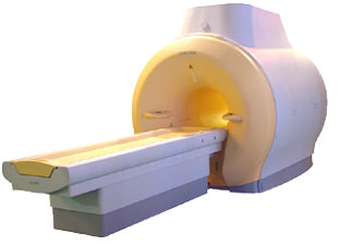
'MRI system is not an expensive equipment anymore. ENCORE developed by ISOL Technology is a low cost MRI system with the advantages like of the 1.0T MRI scanner. Developed specially for the overseas market, the ENCORE is gaining popularity in the domestic market by medium sized hospitals.
Due to the optimum RF and Gradient application technology. ENCORE enables to obtain high resolution imaging and 2D/3D Angio images which was only possible in high field MR systems.'
- Less consumption of the helium gas due to the ultra-lightweight magnet specially designed and manufactured for ISOL. - Cost efficiency MR system due to air cooling type (equivalent to permanent magnetic). - Patient processing speed of less than 20 minutes.'
Device Information and Specification
CLINICAL APPLICATION
Whole body
CONFIGURATION
Short bore compact
Head, C-spine, L-spine, TMJ, Knee, Shoulder, General purpose, Phased Array System: 4 digital receiver channels (Up to 12 channels)
SYNCHRONIZATION
ECG/peripheral: Optional/yes, respiratory gating
SINGLE/MULTI SLICE
Image reconstruction time (2562 ) : 0.02 s
FOV
40 cm
BORE DIAMETER
or W x H
58 cm diameter
MAGNET WEIGHT
3200 kg
H*W*D
200 x 168 x 187 cm
COOLING SYSTEM TYPE
Air-cooled coil and amplifier
CRYOGEN USE
0.05 L/hr helium
STRENGTH
15 mT/m
5-GAUSS FRINGE FIELD
2.3 m / 3.1 m
Passive and active
spacer

• View the DATABASE results for 'ENCORE 0.5T™' (2).Open this link in a new window

MRI Resources 
Health - Safety Training - Equipment - Societies - Breast Implant - Jobs pool
 
Chemical Shift ArtifactInfoSheet: - Artifacts - 
Case Studies, 
Reduction Index, 
etc.MRI Resource Directory:
 - Artifacts -
 
Quick Overview
Please note that there are different common names for this artifact.
Artifact Information
NAME
Chemical shift, black boundary, spatial misregistration, relief
DESCRIPTION
Black or bright band
During frequency encoding, fat protons precess slower than water protons in the same slice because of their magnetic shielding. Through the difference in resonance frequency between water and fat, protons at the same location are misregistrated (dislocated) by the Fourier transformation, when converting MRI signals from frequency to spatial domain. This chemical shift misregistration cause accentuation of any fat-water interfaces along the frequency axis and may be mistaken for pathology. Where fat and water are in the same location, this artifact can be seen as a bright or dark band at the edge of the anatomy.
Protons in fat and water molecules are separated by a chemical shift of about 3.5 ppm. The actual shift in Hertz (Hz) depends on the magnetic field strength of the magnet being used. Higher field strength increases the misregistration, while in contrast a higher gradient strength has a positive effect. For a 0.3 T system operating at 12.8 MHz the shift will be 44.8 Hz compared with a 223.6 Hz shift for a 1.5 T system operating at 63.9 MHz.
mri safety guidance
Image Guidance
For artifact reduction helps a smaller water fat shift (higher bandwidth), a higher matrix, an in phase TE or a spin echo technique. Since the misregistration offset is present in the read out axis the patient may be rescanned with this axis parallel to the fat-water interface. Steeper gradient may be employed to reduce the chemical shift offset in mm. Another strategy is to employ specialized pulse sequences such as fat saturation or inversion recovery imaging. Fat suppression techniques eliminate chemical shift artifacts caused by the lack of fat signal.

See also Black Boundary Artifact and Magnetic Resonance Spectroscopy.
spacer

• View the DATABASE results for 'Chemical Shift Artifact' (7).Open this link in a new window

 
Further Reading:
  Basics:
MRI Artifact Gallery
   by chickscope.beckman.uiuc.edu    
  News & More:
What is chemical shift artefact? Why does it occur? How many Hz at 1.5 T?
   by www.revisemri.com    
Abdominal MRI at 3.0 T: The Basics Revisited
Wednesday, 20 July 2005   by www.ajronline.org    
MRI Resources 
Devices - Spine MRI - Contrast Enhanced MRI - Service and Support - Mobile MRI Rental - Homepages
 
Turbo Inversion RecoveryInfoSheet: - Sequences - 
Intro, 
Overview, 
Types of, 
etc.MRI Resource Directory:
 - Sequences -
 
( TIR / TIRM / IR-TSE - Inversion Recovery Turbo Spin Echo / FIR - Fast Inversion Recovery)
A turbo / fast spin echo sequence with long TI for fluid suppression (FLAIR) or with short TI for fat suppression (STIR). This sequence allows for a true inversion recovery display that shows the arithmetic sign of the signal.
TIRM means a turboIR with a magnitude display.

See also Inversion Recovery, Inversion Recovery Sequence and Fast Spin Echo.
spacer
 
Further Reading:
  News & More:
Accurate T1 Quantification Using a Breath-hold Inversion Recovery TrueFISP Sequence
2003   by rsna2003.rsna.org    
MRI Resources 
Equipment - Homepages - Pacemaker - Abdominal Imaging - Pediatric and Fetal MRI - Devices
 
Flip Angle
 
(FA) The flip angle a is used to define the angle of excitation for a field echo pulse sequence. It is the angle to which the net magnetization is rotated or tipped relative to the main magnetic field direction via the application of a RF excitation pulse at the Larmor frequency. It is also referred to as the tip angle, nutation angle or angle of nutation.
The radio frequency power (which is proportional to the square of the amplitude) of the pulse is proportional to a through which the spins are tilted under its influence. Flip angles between 0° and 90° are typically used in gradient echo sequences, 90° and a series of 180° pulses in spin echo sequences and an initial 180° pulse followed by a 90° and a 180° pulse in inversion recovery sequences.
spacer

• View the DATABASE results for 'Flip Angle' (37).Open this link in a new window


• View the NEWS results for 'Flip Angle' (1).Open this link in a new window.
 
Further Reading:
  Basics:
What MRI Sequences Produce the Highest Specific Absorption Rate (SAR), and Is There Something We Should Be Doing to Reduce the SAR During Standard Examinations?
Thursday, 16 April 2015   by www.ajronline.org    
Mapping of low flip angles in magnetic resonance(.pdf)
Saturday, 1 January 2011   by www.hal.inserm.fr    
  News & More:
A practical guideline for T1 reconstruction from various flip angles in MRI
Saturday, 1 October 2016   by journals.sagepub.com    
Clinical evaluation of a speed optimized T2 weighted fast spin echo sequence at 3.0 T using variable flip angle refocusing, half-Fourier acquisition and parallel imaging
Wednesday, 25 October 2006
MRI Resources 
Case Studies - MRI Technician and Technologist Schools - Services and Supplies - Stimulator pool - Knee MRI - Functional MRI
 
previous      6 - 10 (of 19)     next
Result Pages : [1]  [2 3 4]
 Random Page
 
Share This Page
FacebookTwitterLinkedIn

MR-TIP    
Community   
User
Pass
Forgot your UserID/Password ?    


How AI will impact MRI :
only diagnostics 
saving time 
reducing cost 
makes planning obsolete 
reduce human knowledge 
not at all 

Look
      Ups


MR-TIP.com uses cookies! By browsing MR-TIP.com, you agree to our use of cookies.

Magnetic Resonance - Technology Information Portal
Member of SoftWays' Medical Imaging Group - MR-TIP • Radiology-TIP • Medical-Ultrasound-Imaging • 
Copyright © 2003 - 2024 SoftWays. All rights reserved. [ 28 April 2024]
Terms of Use | Privacy Policy | Advertising
 [last update: 2024-02-26 03:41:00]